|
| Pre-Commissioning Checks & Commissioning Procedure |
| |
ON RECEIVING THE CHARGER : -
THE BATTERY CHARGER WILL BE RECEIVED AT SITE / CLIENT
PREMISES IN A WOODEN PACKING BOX (AS SHOWN IN FIG.-1). FIRST BRING THE MATERIAL TO
THE GROUND LEVEL OR TO THE DESTINATION PLACE CAREFULLY SO THAT THE MATERIAL
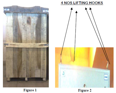
SHOULD NOT GET DAMAGED. THEN UNPACK THE CHARGER. IF ANY FURTHER DISPLACEMENT IS
REQUIRED THEN CARRY THE EQUIPMENT THROUGH ALL FOUR LIFTING HOOKS (AS SHOWN
IN FIG.-2) & NOT BY ANY ONE HOOK. |
 |
AFTER UNPACKING THE CHARGER CAREFULLY EXAMINE ANY POSSIBLE DAMAGE THAT MAY
OCCUR IN TRANSIT. IF ANYTHING IS FOUND DAMAGED REPLACE IT AT THE EARLIEST. OPEN THE
PANEL AND CHECK ALL CONNECTIONS AND THE MOUNTING CONDITIONS OF RELAYS AND
PRINTED CIRCUIT BOARDS. |
| |
INPUT CABLE CONNECTION TO CHARGER : -
- Check the insulation of the charger input lines (marked R, Y & B) with a 500 Volts
megger / good avometer in the higher resistance scale.
- The insulation resistance should be more than 2 M-ohms.
- Check the input supply voltage. This should be within 415 Volts ± 10%, or as specified.
- Check the phase sequence.
- If found O.K. then connect the line at the input terminals.
- The panel should be properly earthed thru' the earthing terminals.
- Without connecting any load first switch on the input circuit breaker.
- Check all the output voltages and indication lamps.
FLOAT MODE CHECK :-
- Keep the auto / manual selector switch to manual position.
- Connect light load to the output terminal.
- Switch on input and output SWITCH/MCCB/MCB/SFU.
- Input and output indicating lamps should glow.
- Voltmeter and ammeter should indicate voltage and current.
-
If any adjustment in the output voltage/current is required, the setting of the
potentiometer provided on the front door of the panel should be adjusted to set the
voltage/current at the required value.
-
Do not temper the setting of any other potentiometer, which may otherwise lead to
serious malfunctioning of the charger.
- If the above tests are O.K. switch off the input SWITCH/MCCB/MCB/SFU.
BOOST MODE CHECK :-
- Connect the same load as float mode to the terminals marked B+ & B-.
- Keep the auto/manual selector switch to manual position.
- Keep the mode Selector Switch in boost position/toggle switch in on position for
selecting the charger in boost mode.
- Switch on input and output Switches/MCB/MCCB/SFU.
- Input and output indicating lamps should glow.
- Voltmeter and ammeter should indicate some voltage and current.
- If any adjustment in the output voltage/current is required, the setting of the
potentiometer should be adjusted.
- Do not temper the setting of any other potentiometer, which may otherwise lead to
serious malfunctioning of the charger.
- If the above tamper tests are O.K. switch off the input SWITCH/MCB/MCCB/SFU.
After checking both the charger in manual mode, keep auto/manual selector switch in
auto position for normal operation.
SPECIAL NOTE
-
The operation of the charger will become erratic if the input connections to the
charger are done with wrong phase sequence.
-
For initial charging of the battery, strictly follow the procedure mentioned in the
battery manual and proper supervision by qualified personnel is absolutely essential.
-
Please ensure constant manual supervision during manual operation (either in Float
mode or in Boost mode) by trained & knowledgeable personnel as system malfunction
may occur due to mal operation. It is highly recommended to keep both chargers in
Auto Mode under normal operating condition.
|
| |
|