| |
| Products : |
| |
|
| |
| |
| |
| |
: Cable trays for speedy and economical installation of
heavy electrical cables and wiress : |
| |
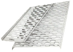 |
Deer Industries -Cable Trays replace the conventional method of running cable underground or Overhead and can be fixed to any structure Wooden plank, Brickwall or Steel Angel. Throughout perforations provide on inbuilt cooling system. Easy to install and easy for repair and replacement. Adopts to any change in layout. Easy to locate and work on cables. No welding and drilling required. Cable trays is the modern system to run cables all over the world.
|
| Material |
: |
Fabricated from mild steel, HR Sheet, Aluminium etc. as per customer specifications. |
| Width |
: |
25 mm - 1000mm |
| Length |
: |
1500 mm, 2000 mm, 2500 mm & 3000mm |
| Finish |
: |
Painted with one coat of Red Oxide or stove enamel grey paint or epoxy paint or Hot dip galvanised or as per customer specification. |
| Thickness |
: |
3mm - 1.3mm |
| |
|
|
* Non standard sizes can be supplied against specific enquiries as well for support do contact us.
* Typical perforation depending upon the customer specification can be made against specific enquiries. |
|
Schedule of permissible loads
All figures given represent the maximum permissible
uniformly distributed load in kgs. per running meter
Unsupported Free Span |
| |
|
| W |
|
Size |
|
H |
600 mm |
1200 MM |
1800 mm |
2500 mm |
| 100 mm |
x |
1.6 mm |
x |
50 mm |
1430 |
355 |
156 |
87 |
| 150 mm |
x |
1.6 mm |
x |
50 mm |
1458 |
362 |
159 |
88 |
| 225 mm |
x |
1.6 mm |
x |
50 mm |
1498 |
371 |
160 |
89.4 |
| 300 mm |
x |
1.6 mm |
x |
50 mm |
1540 |
380 |
162 |
91.3 |
| 375 mm |
x |
2 mm |
x |
50 mm |
1955 |
483 |
210 |
116.7 |
| 450 mm |
x |
2 mm |
x |
50 mm |
1958 |
483 |
210 |
110.7 |
| 600 mm |
x |
2mm |
x |
50 mm |
1964 |
481 |
208 |
110.4 |
| 300 mm |
x |
2mm |
x |
62.5mm |
2680 |
664 |
290 |
16.1 |
| 375 mm |
x |
2mm |
x |
62.5mm |
2685 |
664 |
290 |
161.3 |
| 450 mm |
x |
2mm |
x |
62.5mm |
2689 |
664 |
289 |
158.9 |
| 600 mm |
x |
2mm |
x |
62.5mm |
2698 |
664 |
289 |
157.1 |
| 750 mm |
x |
2mm |
x |
62.5mm |
2707 |
666 |
287 |
155.7 |
| 900 mm |
x |
2mm |
x |
62.5mm |
2716 |
667 |
287 |
153.7 |
| 600 mm |
x |
2mm |
x |
75 mm |
3491 |
861 |
377 |
206.5 |
| 750 mm |
x |
2mm |
x |
75 mm |
3513 |
868 |
377 |
205.02 |
| 900 mm |
x |
2mm |
x |
75 mm |
3535 |
874 |
378 |
205.02 |
|
Formula
The maximum permissible point load at-mid-span may be obtained from the formula
P= ½ X U X C
Where P = maximum permissible point load in kgs. at mid-span.
U = maximum permissible uniformly distributed load in kg per running meter.
S = the particular free span in meter
Free Span Exceeding 16ft. are not recommended. |
| |
| |
|
|
| |
|
Back >> |