JMK Curved Tooth Flexible Gear Couplings are the result of many years of experience in the field of Mechanical Power Transmission.
These Gear Couplings are distinguished by their mechanical flexibility and compensation of Angular, Parallel and Axial misalignments of the connected shafts. They are made for extensive use in Metal Rolling Mills, Paper Machinery, Cranes, Dredgers, Rubber and Plastic Industries, Cement Plants, Conveyors and Elevators, Compressors, Fans and Blowers, Screens and other general industries.
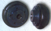
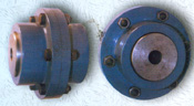
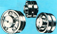
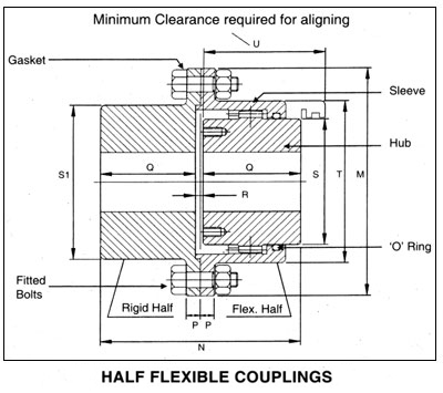
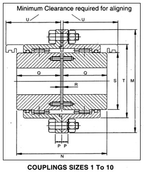
Flexible Gear Couplings basically consist of two hubs, with crowned external teeth and two outer sleeves with internal spur teeth.
Gear Hubs and the outer sleeves are manufactured from carbon steel and are hardened to the required degree. They are machined to fine tolerance for proper meshing of the gears as well as for inter-changeability.
HUBS :
The teeth of Gear Hubs are crowned and are generated by involute system. The amount of crowning and backlash values are so chosen as to ensure the best results in torque transmission, greater flexibility and smooth operation.
SLEEVES :
The internal teeth of the sleeves are generated to ensure correct profile. The coupling sleeves are joined together with high tensile steel bolts (class 10.9 IS : 1367).
O' RINGS :
The setting of special 'O' Rings at the ends of coupling hubs prevents leakage of lubricants and entry of dust. The 'O' rings can also withstand high degree of temperature up to 120°C.
SEAL CARRIERS :
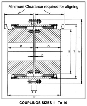
Seal carriers have been provided for sizes from TSW 11 to TSW 19 facilitate inspection and replacement of 'O' rings without disturbing the alignment.
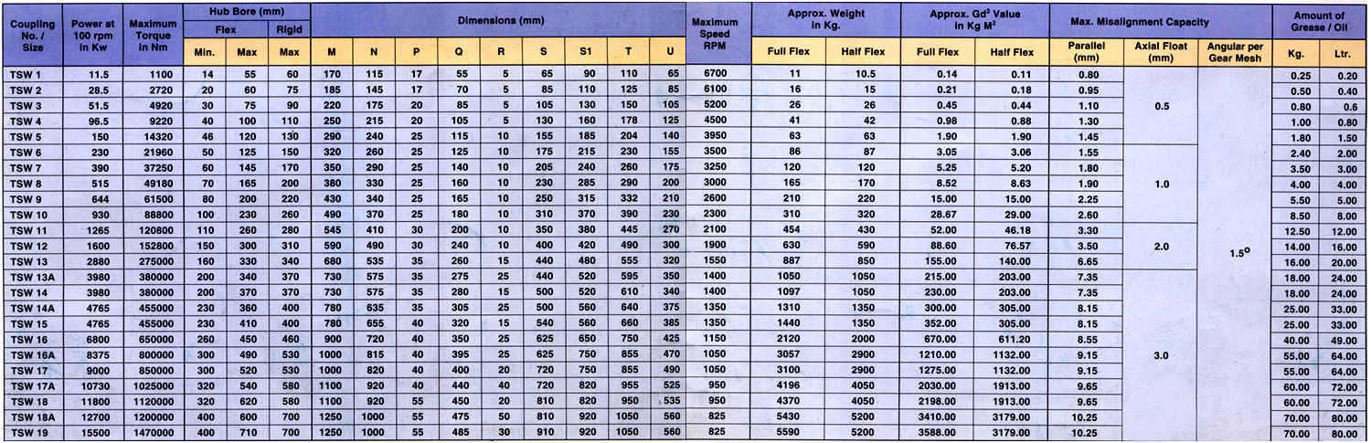
 POWER RATINGS : POWER RATINGS :
The normal power ratings are given in the Table. For selection of the correct size of couplings, proper service factor depending on the type of machines and the peak load should be considered.
SERVICE FACTOR :
Generally, for medium duty use a service factor of 1.5. For heavy duty use a factor of 2 and for extra heavy duty a factor of 3 should be used. For special applications please contact JMK with full details.
LUBRICATION :
The coupling must be filled with grease or oil. It is recommended to use grease where the maximum temperature is within 80°C and for temperature above 80°C, oil should be used.
MISALIGNMENT :
The crowning of the teeth allows the coupling to withstand parallel misalignment up to a maximum of 10.25 mm and angular misalignment up to a maximum of 1.50 per gear mesh. The coupling can also absorb axial displacement of the shafts up to a maximum of 3 mm. |


 << Click for larger view
 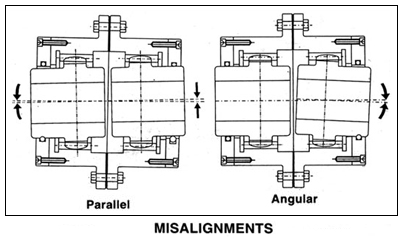 SELECTION OF THE COUPLINGS :
 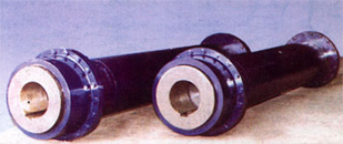 Example : A gear couplings is required to transmit 250 KW from an Electric Motor running at 730 rev/min to a Pulper Machine. Considering the peak load as 180% of full load, the Motor shaft as 100 mm and the Pulper shaft as 110 mm, select a suitable gear coupling.